


Deluge Valve Maintenance Information
Deluge valves are critical components in fire suppression systems designed for high-hazard environments, such as chemical plants, oil refineries, aircraft hangars, and power generation facilities. These valves remain closed under normal conditions but open instantly when triggered, flooding protected areas with water or fire-extinguishing agents to suppress fires before they escalate. Given their mission-critical role, regular maintenance is essential to ensure operational readiness, prevent failures, and comply with safety regulations. This guide outlines key maintenance practices for deluge valves.
Understanding Deluge Valve Operation
Before maintenance, technicians must understand the valve's design and function:
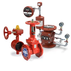
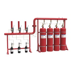
- Components: A typical deluge valve (e.g., Inbal, Tyco, or Victaulic models) includes a main valve body, solenoid actuator, manual override, pressure switches, trim valves, and hydraulic/pneumatic control systems.
- Activation Mechanisms: Deluge valves open via:
- Electrical signals (e.g., smoke/heat detectors triggering a solenoid).
- Pneumatic/hydraulic pressure (e.g., detection tubes rupturing under heat).
- Manual intervention (e.g., emergency pull stations).
- System Integration: Deluge valves are part of deluge sprinkler systems, water spray systems, or water curtains, where pipes are kept dry until activation.
Regular Inspection and Testing Protocols
Maintenance should follow a structured schedule, typically quarterly, semi-annually, and annually, depending on regulatory requirements (e.g., NFPA 25, ISO standards, or local fire codes).
A. Visual Inspections (Monthly/Quarterly)
- Physical Condition: Check for leaks, corrosion, or physical damage to the valve body, piping, and actuators.
- Trim Components: Inspect pilot lines, pressure gauges, and strainers for blockages or debris.
- Manual Override: Verify that the manual release handle operates smoothly without binding.
- Signage: Ensure labeling (e.g., valve ID, flow direction, and control panel connections) is legible.
B. Functional Testing (Semi-Annual/Annual)
- Solenoid Actuation Test:
Energize the solenoid to confirm the valve opens within 5–15 seconds (manufacturer-specific).
Monitor pressure switches to verify they signal activation to the fire panel.
- Manual Override Test:
Engage the manual release to bypass the solenoid, ensuring the valve opens fully.
Reset the valve manually after testing.
- Flow Verification:
Conduct a flow test to confirm the valve delivers the rated discharge (e.g., 300–1,000 GPM for industrial valves).
Check for uneven flow, which may indicate debris or internal damage.
C. Hydraulic/Pneumatic System Checks
- Pilot Line Integrity:
Pressurize pilot lines (if applicable) to detect leaks.
Verify that pressure-sensing devices (e.g., diaphragms, pistons) respond correctly.
- Air/Nitrogen Supply (for Pneumatic Systems):
Check cylinder pressure (if used) and recharge as needed.
Inspect pressure regulators and relief valves.
Troubleshooting Common Issues
- Valve Fails to Open:
Check solenoid power supply, pilot line blockages, or stuck clapper mechanisms.
- False Trips:
Inspect pressure switches for calibration drift or pilot line leaks.
- Leakage:
Tighten flange bolts, replace seals, or repair damaged valve bodies.
Corrosion Prevention and Environmental Controls
- Coating and Painting:
Repaint valve bodies and piping with corrosion-resistant epoxy if the original finish is compromised.
Use sacrificial anodes in marine or high-salinity environments.
- Temperature Control:
Install freeze protection (e.g., heat tracing) in cold climates to prevent valve freezing.
Shield valves from direct sunlight or chemical exposure to prevent material degradation.
- Drainage and Venting:
Ensure drain valves are operational to prevent water accumulation in pilot lines.
Vent trapped air in hydraulic systems to avoid false trips.